Cell Monitoring Unit
CMU - QUT Motorsport
Joint project with Thomas Hulbert
Introduction
The CMU performs several critical functions:
- Communicates with slave cell monitoring units via IsoSPI
- Filters and monitors cell voltages and temperatures
- Executes cell balancing algorithms
- Interfaces with the charger for state management and precharge commands
- Manages shutdown interfaces for IMD, PDOC, connector interlocks, and BMU battery state with detection capabilities
Design Requirements
FSAE Rules 2023
At QUT Motorsport, the 'Accumulator Management System' combines the BMU and CMU.
The AMS system must have galvanic isolation at every segment to segment boundary.
IPC Design Clearance Specifications
- 0.6mm spacing for nets ≥31V
- 0.1mm for nets ≤30V
Team Design Requirements
Revision B - QEV-3 Only
Previous generation used a BMU chip, microcontroller, and CANbus architecture. Revision B addressed systemic issues, monitoring 10 of 14 cells and integrating with the QEV-3 battery assembly position.
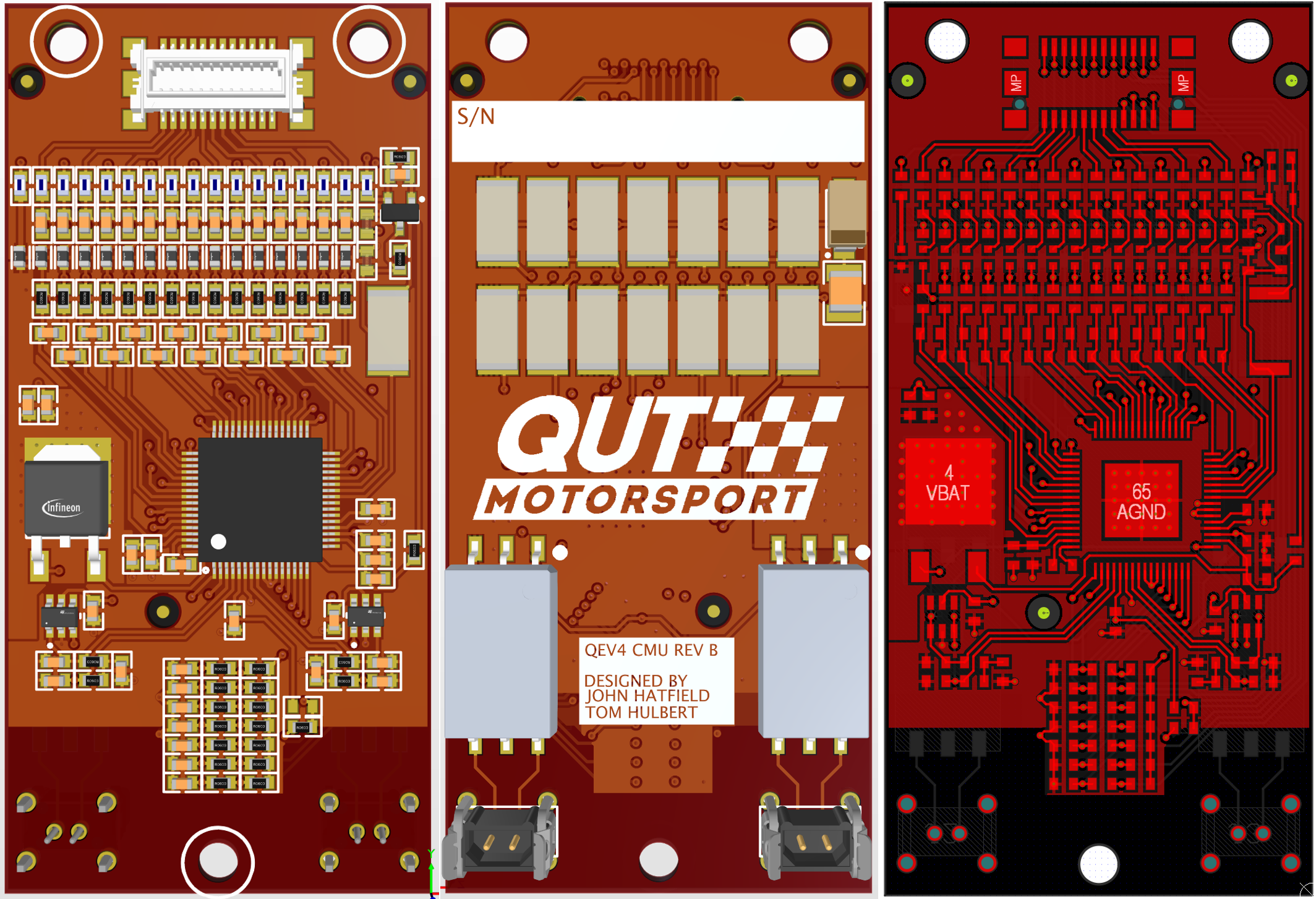
Revision C
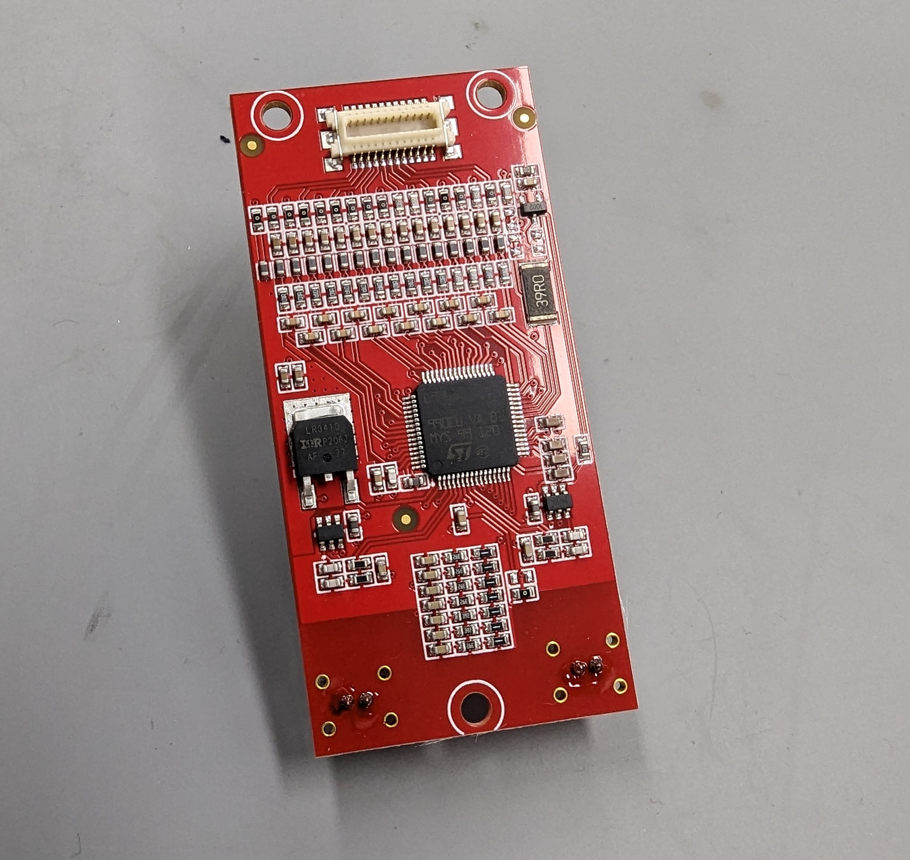
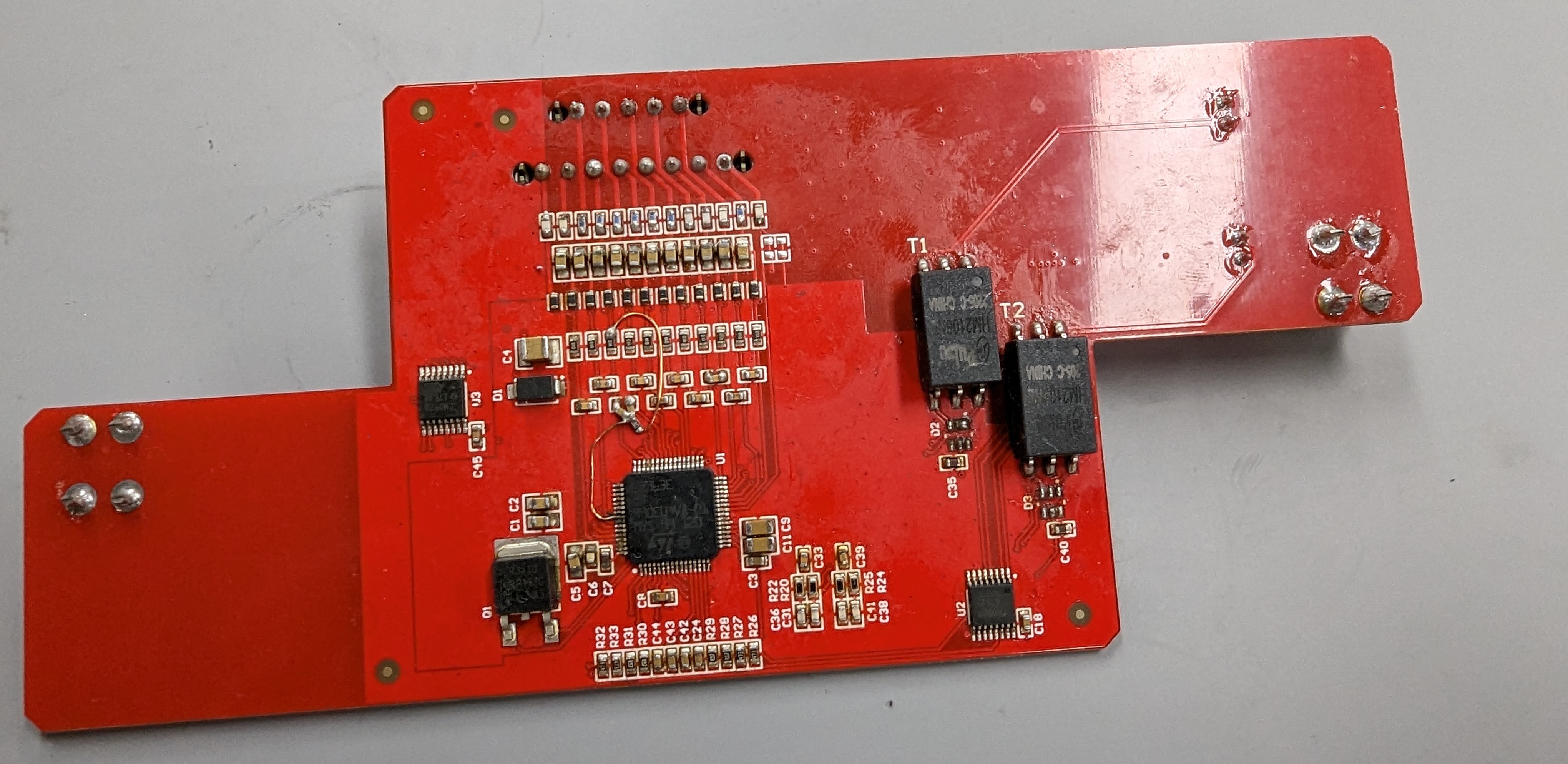
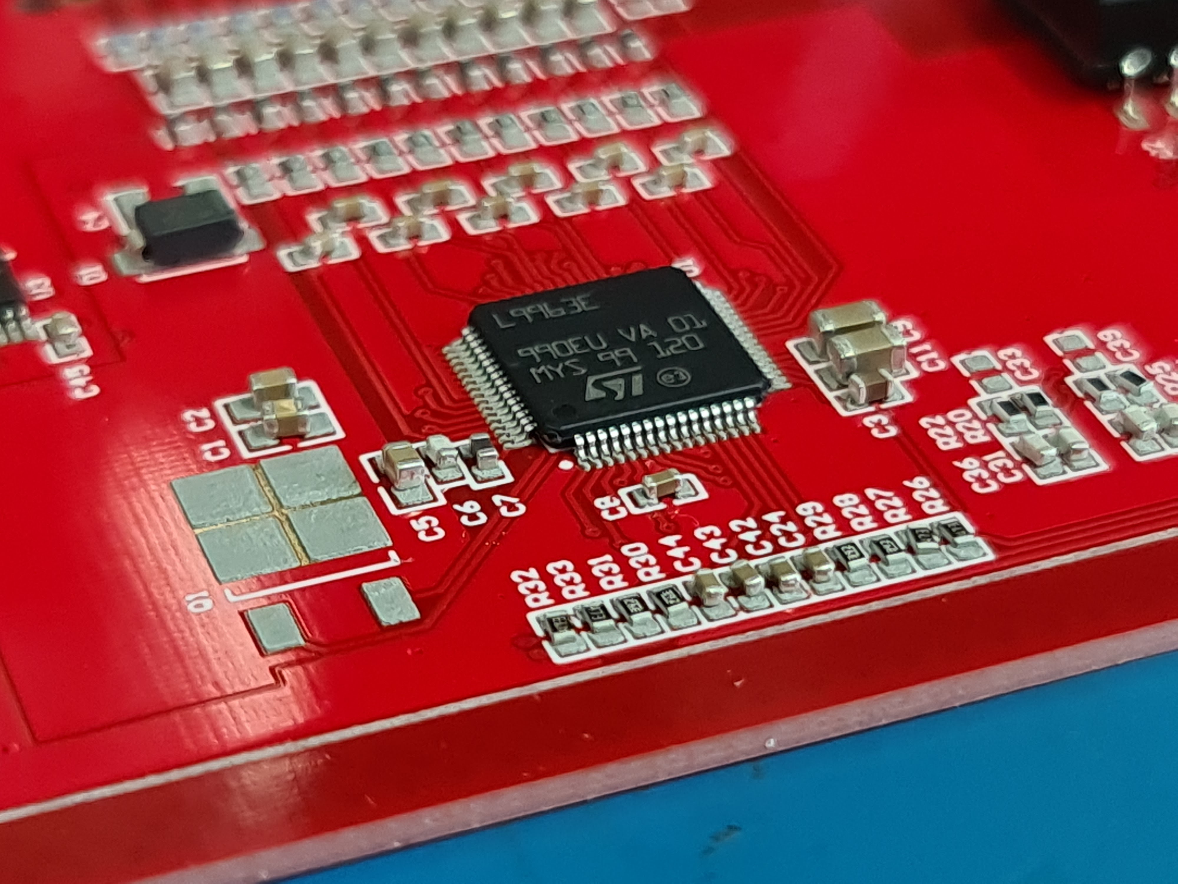
Designed for the QEV-4 vehicle with all 14 cells required. The L9963E implementation features a compact, double-sided design fitting atop the battery assembly with board-to-board connector or custom flex cable compatibility.
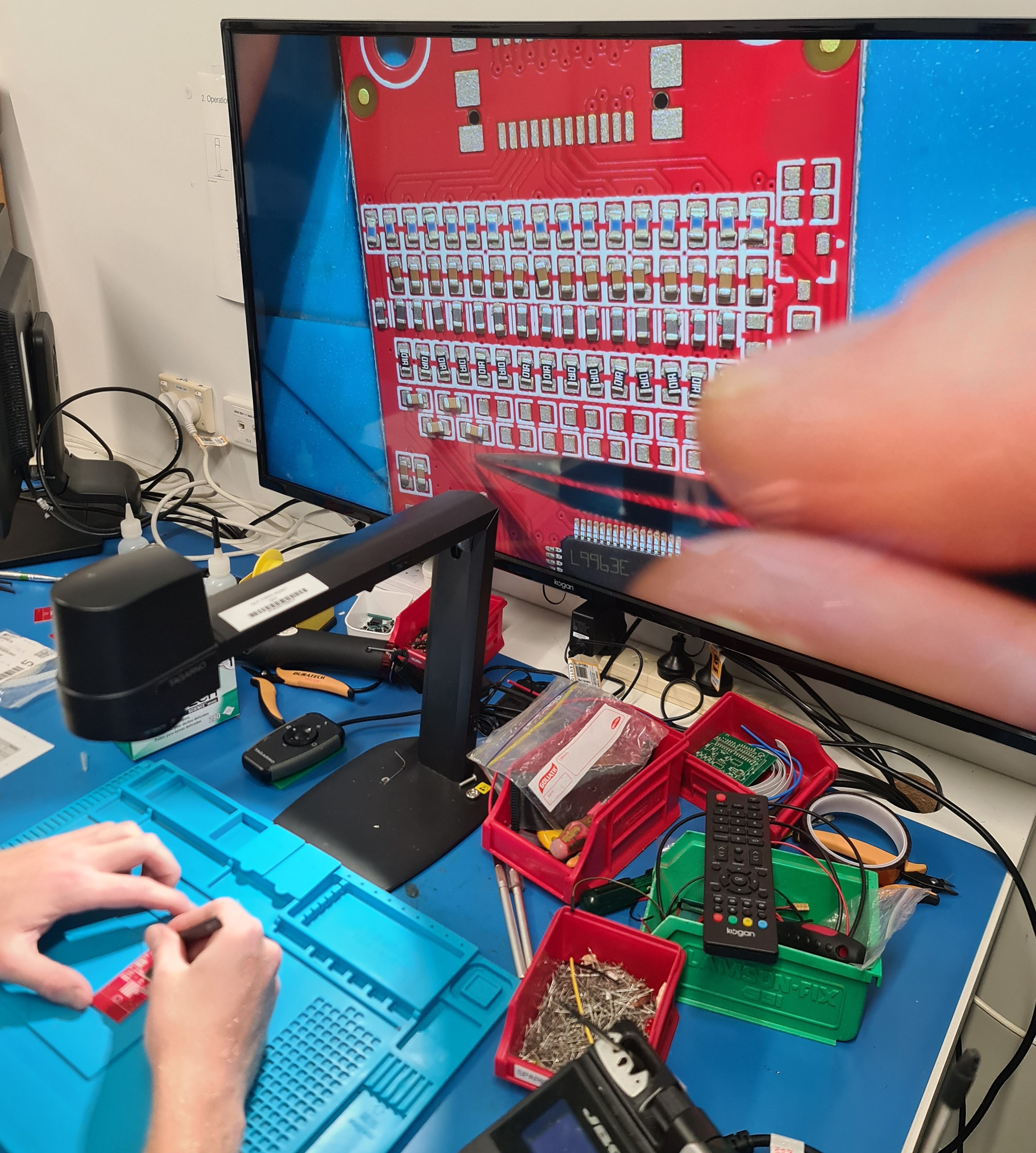
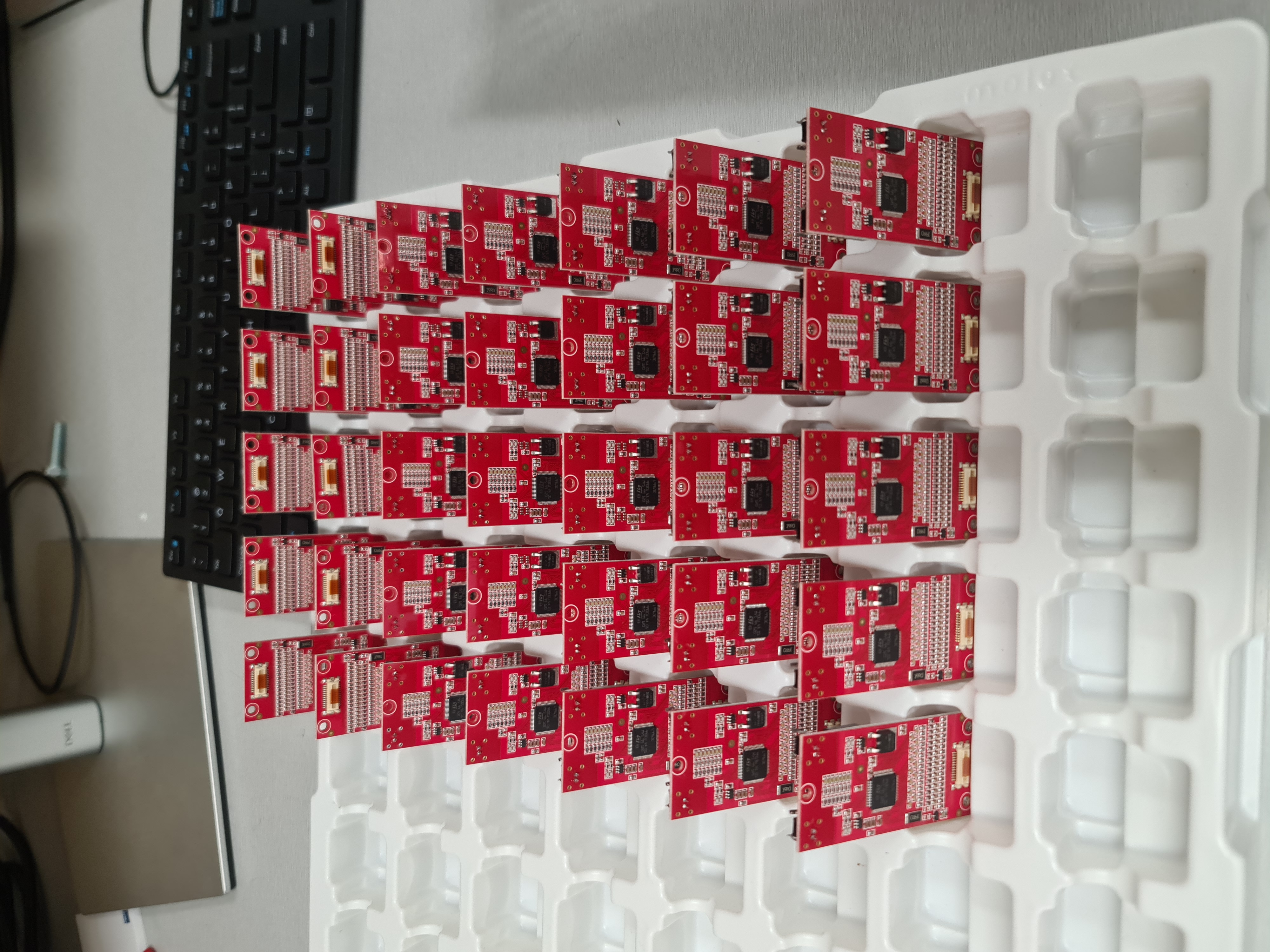
Prototype Assembly & Testing
Hand-assembled prototypes were reflowed in a vapor phase oven and validated using breakout boards for cell voltage and temperature readings.
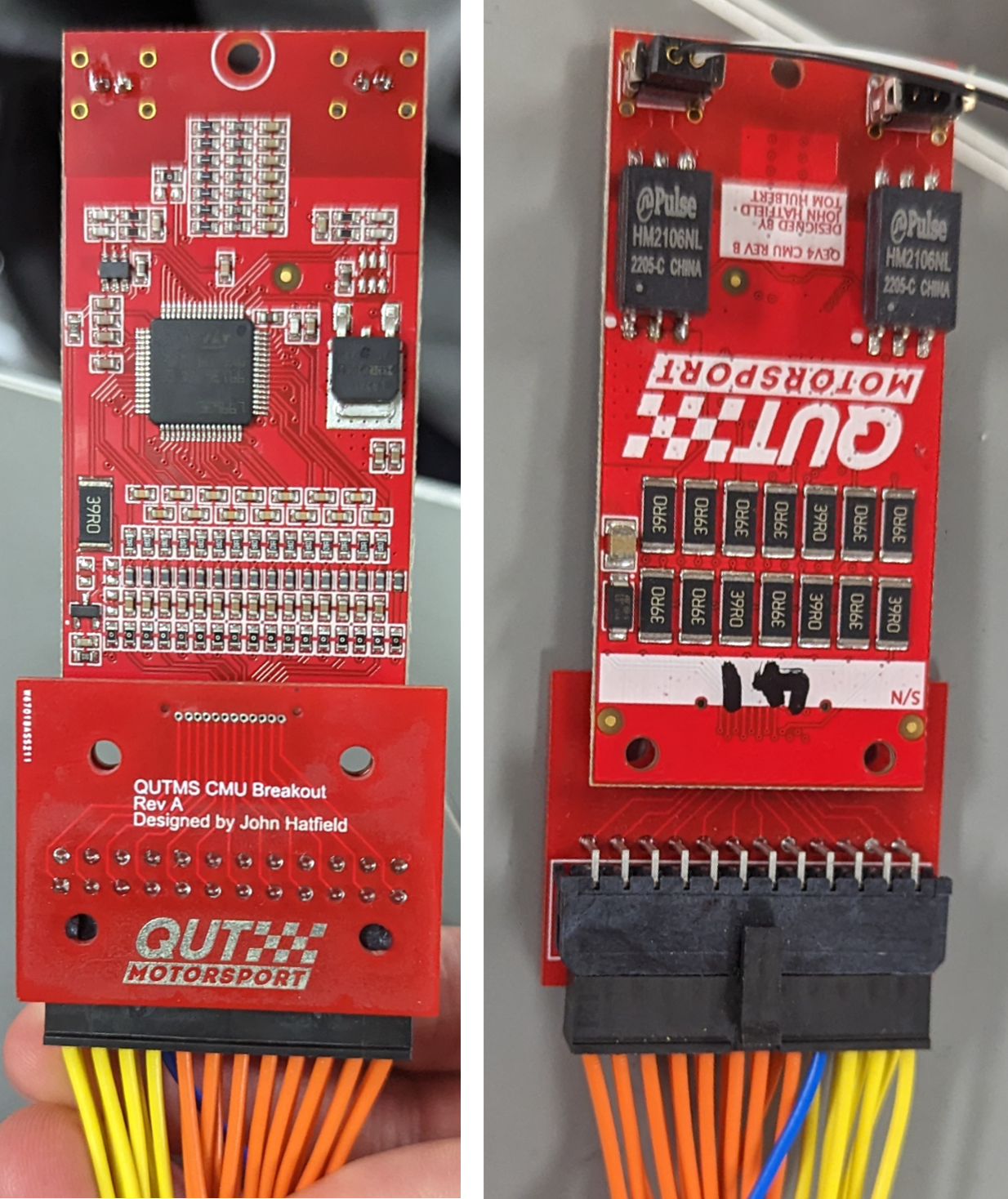
QEV-3 Adaptor
A carrier board connects 10 cells, ties remaining cells, and includes temperature multiplexing for the larger battery assembly.
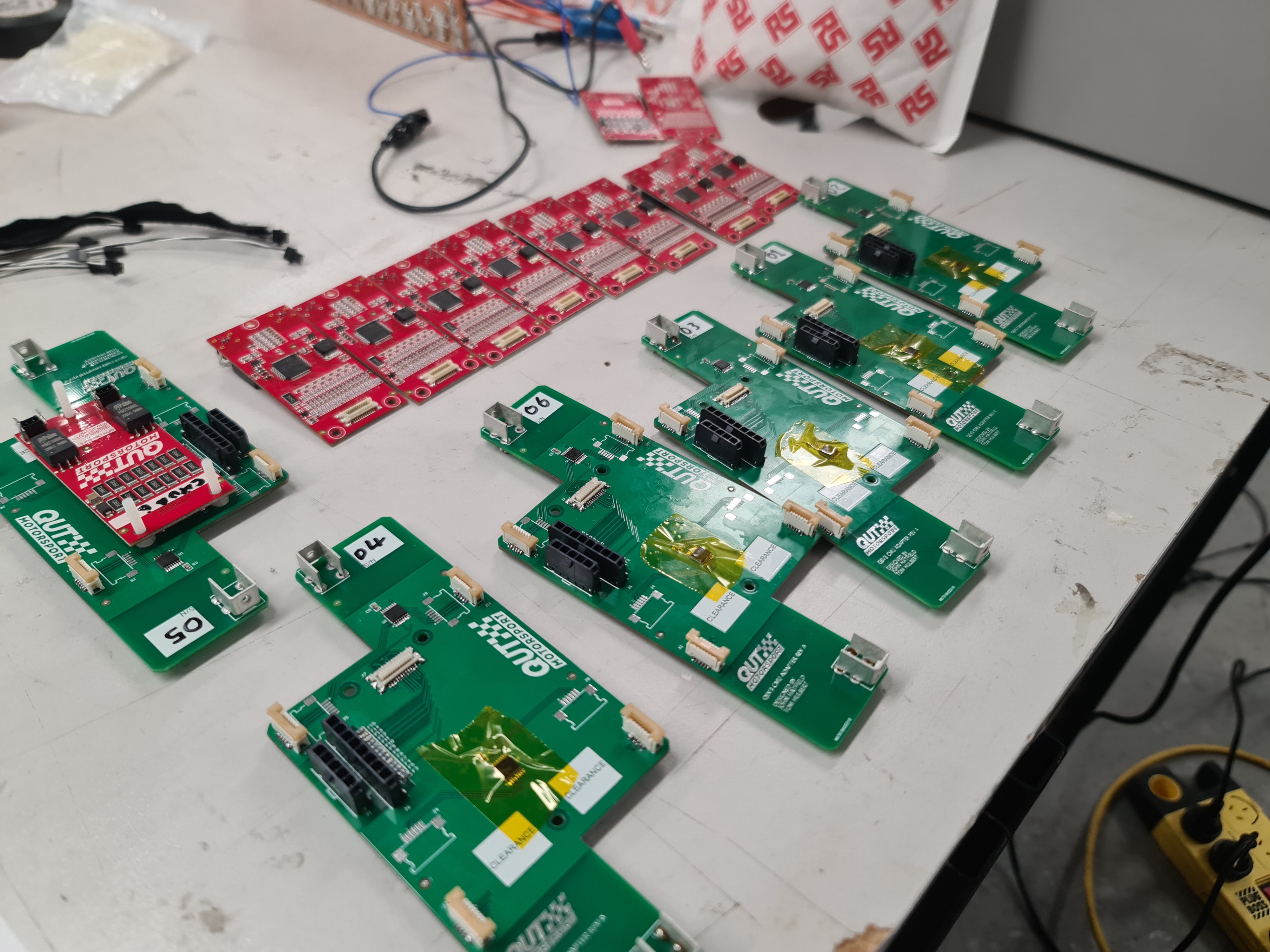
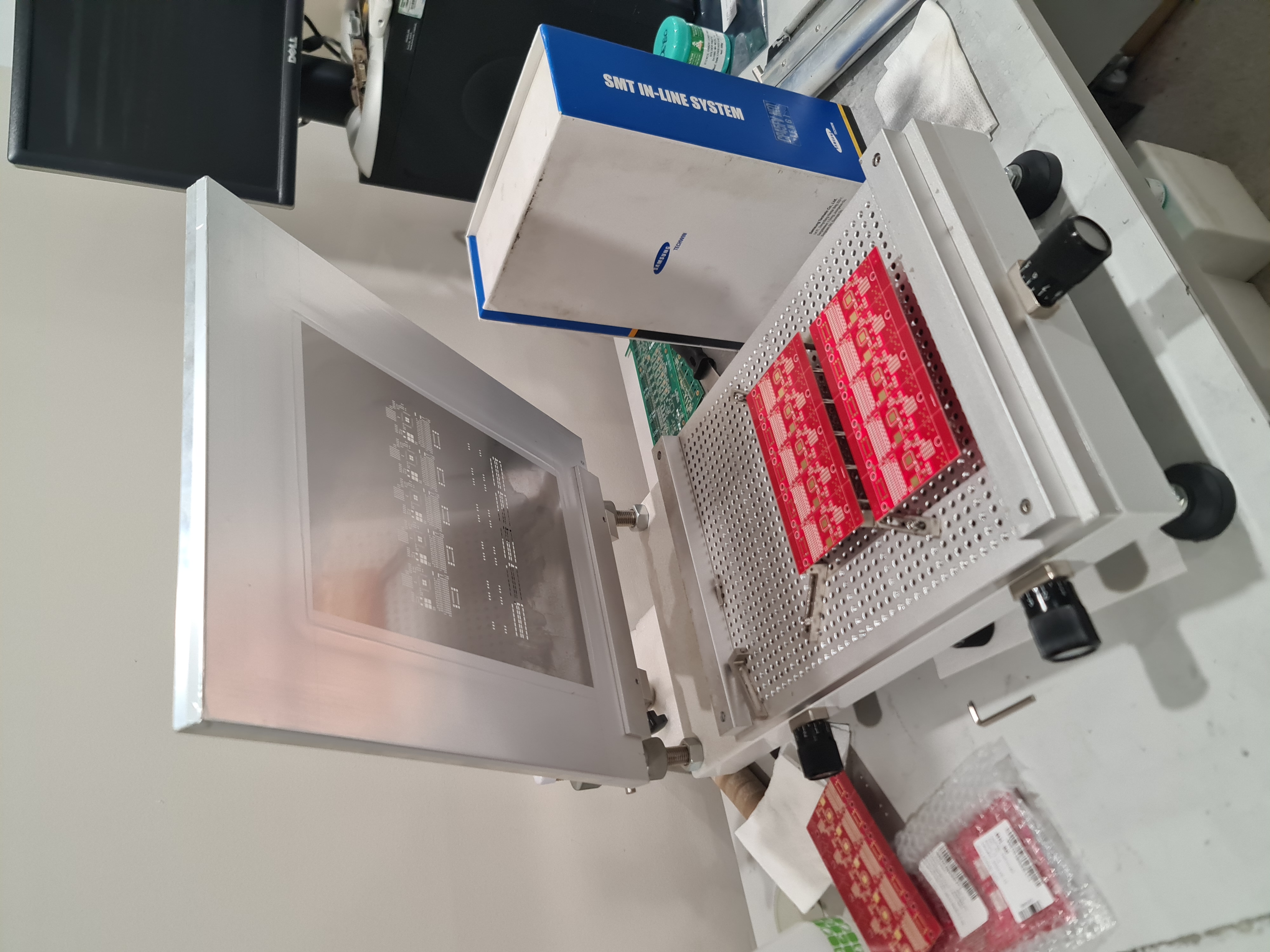
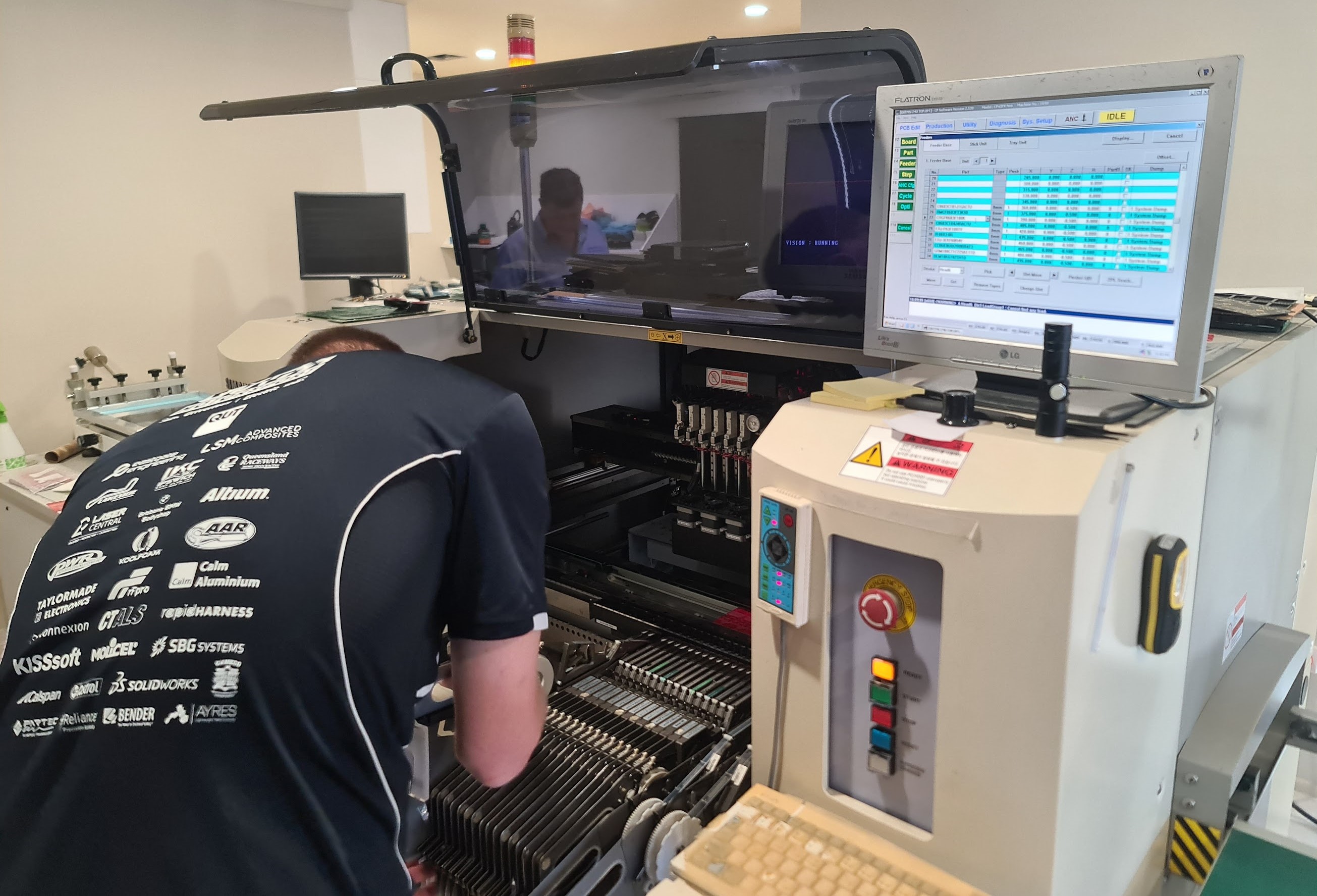
Pick and Place Assembly
Collaboration with Taylormade Electronics produced CMUs for QEV-3, QEV-4, and spares.
Schematics
Not published. Contact for details.